Technical Information
Correct Fitting of Over-Centre Fasteners
Before using an over-centre fastener or toggle latch on your product, it
is important to appreciate how such a fastener works. Our experience has
often shown faulty fittings and unsatisfactory performance originating
in the design stage of the product. The consideration of a few important
points before finalising your product design can prevent having to pack
out or bend a toggle fastener at a later stage to make it function
properly. Consider:-
-
How much pull or pressure is required?
-
How much throw or clearance between the catch and the claw of the
latch in the open position is required?
-
What are the relative positions of the mounting surface and the
point where the claw engages?
-
Is corrosion a problem?
-
Is vibration a problem?
-
Can points of attachment, particularly on castings and mouldings be
incorporated in the design and thus eliminate riveting and welding?
We draw your attention particularly to point 3. The correct locking
position (i.e. when the toggle latch has gone over the centre and locked
fully home) is an angle between 12º and 15º over centre. If this angle
is too great then much of the pressure is lost. However if this angle is
much less there is certainly more pull but the catch is not securely
locked.
Please note with point 5 that is the product is subject to vibration,
consideration should be given to the use of a flex link rather than a
straight link or claw. This would give a more secure locking under those
circumstances.
For further technical advice on these matters please contact us.
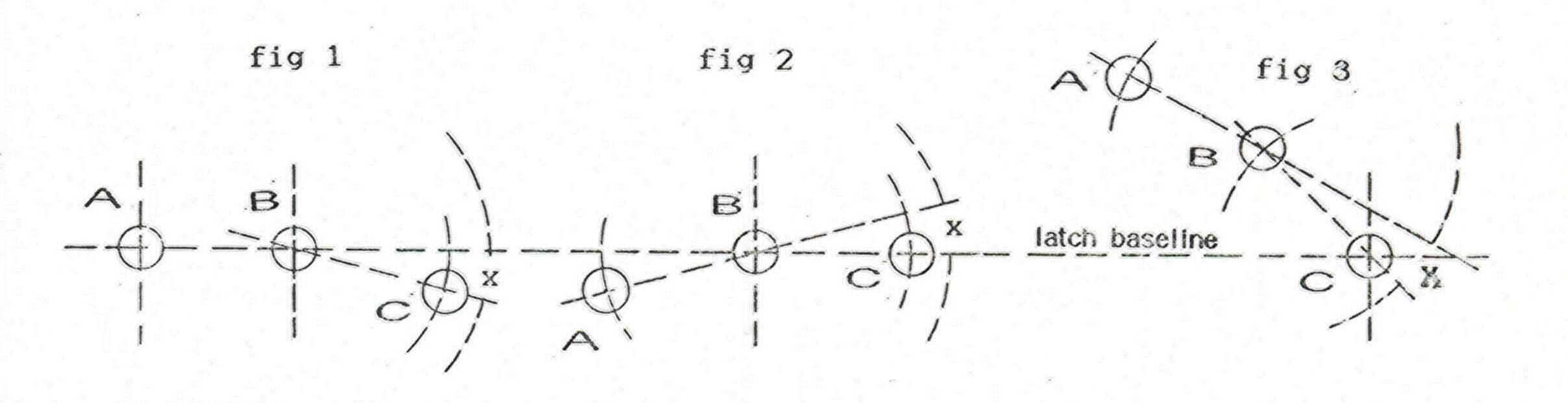
In a normal situation where the point of attachment (A) is in line with
the base of the toggle latch (see figure 1) all standard toggle latches
can be used. The locking angle (x) is approximately 15º
In a situation where the point of attachment (A) is well past the
mounting surface (see figure 2) some pressure may be lost through the
excessive over centre movement. If a straight wire link is
used the connection may be slack. To minimise these possibilities the
attachment hole (C) can be pierced on the centre line of the pivoting
hole (B) and thus decrease the over centre movement.
In a situation where the point of attachment (A) is above the mounting
surface (see figure 3) the two angle toggle latches (S3-B3A/L2 or
S3-B1A/L2) could be used. These toggle latches can be formed at their
base to the correct angle to reach the point of attachment (A) thus
maintaining the correct locking angle.